
We come across Liquid Crystal Display (LCD) displays everywhere around us. Computers, calculators, television sets, mobile phones, digital watches use some kind of display to display the time.
An LCD screen is an electronic display module that uses liquid crystal to produce a visible image. The 16×2 LCD display is a very basic module commonly used in DIYs and circuits. The 16×2 translates o a display 16 characters per line in 2 such lines. In this LCD each character is displayed in a 5×7 pixel matrix.

16X2 LCD pinout diagram

Pin No. | Function | Name |
| 1 | Ground (0V) | Ground |
| 2 | Supply voltage; 5V (4.7V – 5.3V) | Vcc |
| 3 | Contrast adjustment; the best way is to use a variable resistor such as a potentiometer. The output of the potentiometer is connected to this pin. Rotate the potentiometer knob forward and backwards to adjust the LCD contrast. | Vo / VEE |
| 4 | Selects command register when low, and data register when high | RS (Register Select ) |
| 5 | Low to write to the register; High to read from the register | Read/write |
| 6 | Sends data to data pins when a high to low pulse is given; Extra voltage push is required to execute the instruction and EN(enable) signal is used for this purpose. Usually, we set en=0, when we want to execute the instruction we make it high en=1 for some milliseconds. After this we again make it ground that is, en=0. | Enable |
| 7 | 8-bit data pins | DB0 |
| 8 | DB1 | |
| 9 | DB2 | |
| 10 | DB3 | |
| 11 | DB4 | |
| 12 | DB5 | |
| 13 | DB6 | |
| 14 | DB7 | |
| 15 | Backlight VCC (5V) | Led+ |
| 16 | Backlight Ground (0V) | Led- |
RS (Register select)
A 16X2 LCD has two registers, namely, command and data. The register select is used to switch from one register to other. RS=0 for command register, whereas RS=1 for data register.
Command Register: The command register stores the command instructions given to the LCD. A command is an instruction given to LCD to do a predefined task. Examples like:
- initializing it
- clearing its screen
- setting the cursor position
- controlling display etc.
Processing for commands happens in the command register.
Data Register: The data register stores the data to be displayed on the LCD. The data is the ASCII value of the character to be displayed on the LCD. When we send data to LCD it goes to the data register and is processed there. When RS=1, data register is selected.
Important command codes for LCD
| Sr.No. | Hex Code | Command to LCD instruction Register |
| 1 | 01 | Clear display screen |
| 2 | 02 | Return home |
| 3 | 04 | Decrement cursor (shift cursor to left) |
| 4 | 06 | Increment cursor (shift cursor to right) |
| 5 | 05 | Shift display right |
| 6 | 07 | Shift display left |
| 7 | 08 | Display off, cursor off |
| 8 | 0A | Display off, cursor on |
| 9 | 0C | Display on, cursor off |
| 10 | 0E | Display on, cursor blinking |
| 11 | 0F | Display on, cursor blinking |
| 12 | 10 | Shift cursor position to left |
| 13 | 14 | Shift cursor position to right |
| 14 | 18 | Shift the entire display to the left |
| 15 | 1C | Shift the entire display to the right |
| 16 | 80 | Force cursor to beginning ( 1st line) |
| 17 | C0 | Force cursor to beginning ( 2nd line) |
| 18 | 38 | 2 lines and 5×7 matrix |
Displaying Custom Characters on 16X2 LCD
Generating custom characters on LCD is not very hard. It requires the knowledge about custom generated random access memory (CG-RAM) of LCD and the LCD chip controller. Most LCDs contain Hitachi HD4478 controller.
CG-RAM is the main component in making custom characters. It stores the custom characters once declared in the code. CG-RAM size is 64 byte providing the option of creating eight characters at a time. Each character is eight byte in size.
CG-RAM address starts from 0x40 (Hexadecimal) or 64 in decimal. We can generate custom characters at these addresses. Once we generate our characters at these addresses, we can print them by just sending commands to the LCD. Character addresses and printing commands are below.

In the table above you can see starting addresses for each character with their printing commands.
The first character is generated at address 0x40 to 0x47 and is printed on LCD by just sending a command 0.
The second character is generated at address 0x48 to 0x55 and is printed by sending a command 1.
How to Generate Custom Characters in CG-RAM
In LCD displays, each character is in a 5×8 matrix. Where 5 are the number of columns and 8 is the number of rows.

Here is a simple example of how to create letter ‘b’ in CG-RAM.
The Array for generating ‘b’ is char b[7]={0x10,0x10,0x16,0x19,0x11,0x11,0x1E}; That is,
- Send address where you want to create character.
- Now create your character at this address. Send the ‘b’ character array values defined above one by one to the data register of LCD.
- To print the generated character at 0x40. Send command 0 to command register of LCD. The table below would explain this more clearly

Interfacing a 16X2 LCD with Arduino
LCD modules form a very important in many Arduino based embedded system designs to improve the user interface of the system. Interfacing with Arduino gives the programmer more freedom to customise the code easily. Any Arduino board, a 16X2 LCD display, jumper wires and a breadboard are sufficient enough to build the circuit. The interfacing of Arduino to LCD display below.

Source code for 16X2LCD and Arduino.
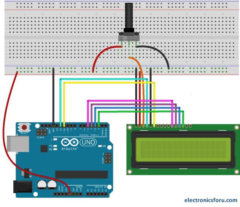
Display the LED Brightness on a 16×2 LCD
The combination of an LCD and Arduino yields several projects, the most simple one being LCD to display the LED brightness. All we need for this circuit is an LCD, Arduino, breadboard, a resistor, potentiometer, LED and some jumper cables. The circuit connections are below.

The detailed project is available at displaying brightness of a LED on an LCD display
This article was first published on 21 November 2016 and was recently updated on 17 July 2021.


 and their use in electrical installations | NICEIC")


