
ATmega328p micrcontroller Timer/Counter can be used to generate PWM signal. There are two types of PWM signal that can be generated which are Fast PWM and Phase Correct PWM. The Fast PWM mode is used for power regulation, rectification, and DAC applications. In this tutorial we will explain and illustrate Fast PWM mode for Timer/ Counter 0 with example codes.
We had explained in earlier tutorial the other modes of operation. For normal mode see the tutorial ATmega328p Timer Programming Examples. For CTC mode see the Programming ATmega328p in CTC mode tutorial.

Precaution:
The website https://electricianworldnews.com has been stealing content without consent from this ee-diary
weblog(http://ee-diary.blogspot.com) and therefore information there
may not be accurate, so for original content go to ATmega328P Fast PWM mode Programming with Example.
Fast PWM mode
The Fast PWM mode is used to generate PWM signal at the output compare pins(either OC0A or OC0B depending upon which output compare unit A or B is used). It is called Fast because the generated PWM signal can have high frequency due to its single-slope operation.
Modes of Fast PWM mode
There are two Fast PWM modes for Timer/Counter 0 unit. They are mode 3 and mode 7 which are selected using the waveform generation mode bits(WGM02, WGM01, WGM00). The following table shows the WGM bits combination for mode 3 and mode 7.

The WGM02 bit is located in the TCCR0B register as shown below.
The WGM01 and WGM00 bits are located in the TCCR0A register as shown below.

The difference between the mode 3 Fast PWM and mode 7 Fast PWM is the TOP value. For mode 3 the TOP value is is 0xFF whereas the the TOP value for mode 7 is OCRA. If mode 7 is used then we have to load count value into the OCR0A register. If mode 3 is used then we don’t have to load the counter since the TOP value in this case is 0xFF. Thus in Fast PWM mode, we have to select either mode 3 or 7. Once selected the counter is started and the timer/counter starts counting from zero to TOP value and when TOP value is reached the counting is repeated from the bottom.
Types of Fast PWM mode
There are two types of Fast PWM modes (a) non-inverting Fast PWM (b) inverting Fast PWM. Which type is used depends upon the setting of the Compare Output Mode bits COM0A1 and COM0A0 bits located in the TCCR0A register. The following table shows how to select the COM0A1 and COM0A0 bits.

Following picture shows the timing diagram for Fast PWM which includes non-inverted and inverted PWM outputs.

Configuring ATmega328P in Non-Inverting PWM mode
In this non-inverting Fast PWM example, we will use the Timer/Counter0 with Output Compare Unit A in mode 7 wave generation mode. That is the TOP value is the count value loaded into the OCR0A register.
The TCCR0A register contains the Wave Generation Mode bits(WGM01 and WGM00) and the Compare Output Mode(COM0A1, COM0A0) bits. The WGM01 and WGM00 in TCCR0A register together with the WGM02 bit in the TCCR0B register are used to set the Fast PWM mode. The COM0A1, COM0A0 bits are used set non-inverting or inverting mode. For this example, these are set as follows.
COM0A1 = 1, COM0A0 = 0, WGM01 = 1, WGM00 = 1
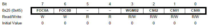
The TCCR0B register contains the WGM02 and clock select bits(CS02, CS01 and CS00). The WGM02 bit is set to 1 for mode 7.
WGM02 = 1
The CS02, CS01 and CS00 bits are used to stop the timer/counter, set pre-scalar value or set external clock source. The following table shows the function of these CS bits.
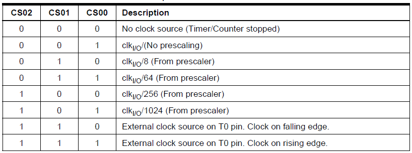
The CS bits for pre-scalar are used to set the Fast PWM frequency. The PWM frequency can be calculated by the following equation:
(F_{w}=frac{F_{osc}}{256N}) —————>(1)
where, (F_{w}) is the frequency of the generated wave and N is the pre-scalar which can have value of 1, 8, 64, 256 and 1024.
For example, using equation (1), if we use pre-scalar N of 1 we can generate Fast PWM signal of frequency 31.25KHz. For this,
CS00 = 1
The count value to be loaded into the OCR0A register depends upon the duty cycle of the required output Fast PWM signal. It is given by the following formula.
(OCR0 = frac{256D}{100} – 1) ————————>(2)
where, D is the Duty cycle that range from 0% to 100%.
For example if we want the PWM signal to have 75% duty cycle then using equation (2), the value for the OCR0A is 191.
Programming ATmega328P in Non-Inverting PWM mode
We can either use the OCR A or OCR B unit of the Timer/Counter 0 to output non-inverting Fast PWM. First we illustrate how to use the OCR A unit for generating non-inverting PWM signal at OC0A pin and then show the same thing at OC0B pin.
Non-Inverting Fast PWM mode 3 using OCR A unit
Once we have the made the decision for what kind of Fast PWM to generate(non-inverting), the frequency and duty cycle we want to generate we can follow the following steps to program ATmega328P for Fast PWM.
(a) Make the OC0A pin(Port D Pin 6) an output pin
DDRD |= (1<<PD6);
(b) Load count value into the OCR0A register for duty cycle control
OCR0A = 191;
(c) Configure TCCR0A and TCCR0B register for (i) non-inverting, (ii) Fast PWM mode, (iii) Pre-scalar for frequency control
TCCR0A |= (1<<COM0A1) | (1<< WGM01) | (1<< WGM00);
TCCR0B |= (1<<WGM02) | (1<<CS00);
The following is then the atmega328p fast pwm C program code for non-inverting Fast PWM with frequency of 31.25KHz and duty cycle of 75% using Timer/Counter0.
#ifndef F_CPU
#define F_CPU 8000000UL
#endif#include <avr/io.h>
int main()
{
DDRD |= (1<<PD6); //Fast PWM output at OC0A pin
OCR0A = 191; // Duty cycle of 75%
TCCR0A |= (1<<COM0A1) | (1<<WGM01) | (1<<WGM00); //Non-Inverting Fast PWM mode 3 using OCR A unit
TCCR0B |= (1<<CS00); //No-Prescalar
while (1);
return 0;
}
The following schematic diagram shows Fast PWM output at the OC0A pin(port D pin 6).

Non-Inverting Fast PWM mode 3 using OCR B unit
The following C program code will output non-inverting Fast PWM signal at the OC0B pin of ATmega328P.
#ifndef F_CPU
#define F_CPU 8000000UL
#endif#include <avr/io.h>
int main()
{
DDRD |= (1<<PD5); //Fast PWM output at OC0B pin
OCR0B = 191; // Duty cycle of 75%
TCCR0A |= (1<<COM0B1) | (1<<WGM01) | (1<<WGM00); //Non-Inverting Fast PWM mode 3 using OCR B unit
TCCR0B |= (1<<CS00); //No-Prescalar
while (1);
return 0;
}
The following schematic diagram shows Fast PWM output at the OC0B pin(port D pin 5).

Non-Inverting Fast PWM mode 7 using OCR B unit as Output
In the mode 7 Fast PWM mode, the OCR0A register is used to hold the TOP value. Thus the output cannot be taken from the OC0A pin hence the output is only from the OC0B pin. Also in case of mode 7 the OCR0B register is used to set the duty cycle of the PWM. Important thing to remember is that the TOP value in OCR0A register must be less or equal to the Duty Cycle value in the OCR0B register.
The following C program illustrates how one can use the ATmega328P microcontroller to set the Fast PWM mode 7 in non-inverting mode with duty cycle of 75%(The duty cycle was calculated using the pwm duty cycle formula provided above)., frequency of 31.25KHz, with TOP value of 200.
#ifndef F_CPU
#define F_CPU 8000000UL
#endif#include <avr/io.h>
int main()
{
DDRD |= (1<<PD5); //Fast PWM output at OC0B pin
OCR0A = 200; // Top Value of 200(must be equal or greater than Duty Cycle)
OCR0B = 191; // Duty cycle of 75%
TCCR0A |= (1<<COM0B1) | (1<<WGM01) | (1<<WGM00); //Non-Inverting Fast PWM mode 7
TCCR0B |= (1<<WGM02) | (1<<CS00); //No-Prescalar
while (1);
return 0;
}
The following circuit diagram shows Fast PWM output at the OC0B pin.

Programming ATmega328P in Inverting PWM mode
Inverted Fast PWM mode 3 using OCR A unit
Below is program code to generate inverted Fast PWM signal at OC0A pin with duty cycle of 75% which is loaded into the OCR0A register and frequency of 31.25KHz. The duty cycle was calculated using the pwm duty cycle formula provided above. To set the inverted mode we have to set both the COM0A1 and COM0A0 bits in the TCCR0A register.
#ifndef F_CPU
#define F_CPU 8000000UL
#endif#include <avr/io.h>
int main()
{
DDRD |= (1<<PD6); //Fast PWM output at OC0A pin
OCR0A = 191; // Duty cycle of 75%
TCCR0A |= (1<<COM0A1) | (1<<COM0A0) | (1<<WGM01) | (1<<WGM00); //Inverting Fast PWM mode 3
TCCR0B |= (1<<CS00); //No-Prescalar
while (1);
return 0;
}
The following circuit diagram shows Fast PWM output at the OC0A pin.

Inverted Fast PWM mode 3 using OCR B unit
Below is program C code to generate inverted Fast PWM signal at OC0B pin
with duty cycle of 75% which is loaded into the OCR0B register(pwm duty cycle formula is provided above) and frequency of 31.25KHz. To use inverted mode we have to set both the
COM0B1 and COM0B0 bits in the TCCR0A register.
#ifndef F_CPU
#define F_CPU 8000000UL
#endif#include <avr/io.h>
int main()
{
DDRD |= (1<<PD5); //Fast PWM output at OC0B pin
OCR0A = 191; // Duty cycle of 75%
TCCR0A |= (1<<COM0B1) | (1<<COM0B0) | (1<<WGM01) | (1<<WGM00); //Inverting Fast PWM mode 3
TCCR0B |= (1<<CS00); //No-Prescalar
while (1);
return 0;
}
The following circuit diagram shows inverted Fast PWM output at the OC0B pin.
Inverted Fast PWM mode 7
For generating inverted Fast PWM in mode 7. We have to use the OCR0A for TOP value for counting. In this case we have loaded OCR0A top value of 200. This top value must be greater than the duty cycle value 191 for 75% duty cycle which is loaded into the OCR0B register. The duty cycle was calculated using the pwm duty cycle formula provided above. In case of mode 7, the output PWM signal is taken from OC0B pin. To use mode 7 we must set all the wave generation mode bits WGM02 located in TCCR0B, WGM01 and WGM00 which are located in TCCR0A register.
Following is the C program code for generating inverted Fast PWM signal in mode 7.
#ifndef F_CPU
#define F_CPU 8000000UL
#endif#include <avr/io.h>
int main()
{
DDRD |= (1<<PD5); //Fast PWM output at OC0A pin
OCR0A = 200; // Top Value of 200(must be equal or greater than Duty Cycle)
OCR0B = 191; // Duty cycle of 75%
TCCR0A |= (1<<COM0B1) | (1<<COM0B0) | (1<<WGM01) | (1<<WGM00); //Inverting Fast PWM mode 7
TCCR0B |= (1<<WGM02) | (1<<CS00); //No-Prescalar
while (1);
return 0;
}
So in this tutorial on generating PWM signals using timers in the atmega328p chip, we have illustrated the Fast PWM mode with example code. In the next tutorial we will show how to use the Phase Correct PWM with ATmega328P.
For other tutorials on PWM see the followings:
Generate Sine Wave using Arduino PWM and Simulink
PWM Application Examples with Arduino Nano
PWM – Programming Arduino using Matlab
DC motor Speed control with Potentiometer and PWM using Arduino


