
Here we will show how to interface HC-05 bluetooth module and ATmega328p and how to use the bluetooth module to turn on/off a LED connected to the ATmega328p microcontroller. To do this we will use a cell phone to communicate with the microcontroller. The cell phone and the bluetooth module will be paired via bluetooth. Then entering character y or n on the cell phone will to transferred to the bluetooth module wirelessly, then the bluetooth module will send the received character to the ATmega328p via USART communication and then ATmega328p will turn on or off the LED accordingly. This simple example can be extended to more complex projects. Once you have learned how to setup the interfacing between the microcontroller and bluetooth module and learned how to communicate with it, other control mechanism can be easily added.
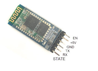
The HC-05 bluetooth module is as shown below.

HC-05 Bluetooth Module has six pins-
– EN(Enable) pin is used put the module into either data mode or command mode. When low the module is in data mode. This is also the default mode. When high the module is put into command mode
– Vcc or +5V pin is the power supply pin
– GND pin is the ground pin
– TX pin is the transmit serial pin where the bluetooth module will transmit data. This pin is 3.3V logic level pin.
– RX pin the receive serial pin where the bluetooth module will receive data. Note that is 3.3V pin w
hich means the signal coming into this pin must be 3.3V logic level.
– State pin is pin which indicates the state of the bluetooth module like whether it is working properly or not. This pin is also connected to the board led so this is quite unnecessary to connect.
HC05 Bluetooth interfacing with ATmega328p schematic diagram
Below picture shows schematic diagram of interfacing the HC-05 bluetooth module with ATmega329p microcontroller.

In the schematic diagram, the ATmega328p USART Tx pin is connected to the Rx pin. Here a voltage divider is used to fed 3.3V logic level to the bluetooth module using the 1KOhm and 2.2KOhm resistors. The ATmega328p USART Rx pin is directly connected to the Tx pin since the ATmega328p is 5V logic and can detect the 3.3V logic signal coming from the HC05 bluetooth module. Similarly the EN pin of the bluetooth is connected to the PORT C pin 5 of the microcontroller. A LED with resistor is connected to the PORT B pin 0. When the Bluetooth module receives message from mobile handset or other device to turn on the LED or turn off the LED, the microcontroller will receive the same message from the bluetooth module and turn on/off the LED.
On a breadboard the connection looks like this.

Programming
The C program code for the bluetooth communication with HC05 module is below.
#ifndef F_CPU/*https://ee-diary.blogspot.com*/
#define F_CPU 8000000UL
#endif#include <avr/io.h>
#define UBRRVAL 51
void usart_init(void);
void sendbyte(unsigned char);
void sendstr(unsigned char *);
unsigned char receivebyte(void);
void receivestr(unsigned char*);unsigned char onmsg[] = "ONn";
unsigned char offmsg[] = "OFFn";
unsigned char defaultmsg[] = "LED Status:n";
unsigned char rxdata;int main(){
DDRB |= (1<<PB0);
usart_init();while(1)
{
rxdata = receivebyte();if(rxdata == 'y')
{
PORTB |= (1<<PB0);
sendstr(defaultmsg);
sendstr(onmsg);}
else if(rxdata =='n')
{
PORTB &= ~(1<<PB0);
sendstr(defaultmsg);
sendstr(offmsg);
}
else{
}
}return 0;
}void usart_init(void){
UBRR0H= (unsigned char)(UBRRVAL>>8); //high byte
UBRR0L=(unsigned char)UBRRVAL; //low byte
UCSR0B |= (1<<TXEN0) | (1<<RXEN0); //Enable Transmitter and Receiver
UCSR0C |= (1<<UCSZ01)|(1<<UCSZ00); //Set data frame format: asynchronous mode,no parity, 1 stop bit, 8 bit size
}void sendbyte(unsigned char MSG){
while((UCSR0A&(1<<UDRE0)) == 0); // Wait if a byte is being transmitted
UDR0 = MSG;
}void sendstr(unsigned char *s){
unsigned char i = 0;
while(s[i] != '�'){
sendbyte(s[i]);
i++;
}
}unsigned char receivebyte(void){
while(!(UCSR0A & (1<<RXC0)));
return UDR0;
}
The HC05 bluetooth module operates at 9600 baud rate with 8 bit data and 1 stop bit. So accordingly we have set up the ATmega328p USART for the same serial communication settings. The ubrr value of 51 used in the program setup up the baud rate for 9600 using 8MHz CPU frequency, see datasheet for this.
The codes used here are explained in our earlier tutorial Programming ATmega328p USART. It explains basic of ATmega328p USART programming by showing example of how to use a PC terminal to send command
to the microcontroller usart to turn on/off a led. Also see Communication between Microcontrollers using USART-ATmega328P and ATmega32A tutorial which explains how to use the Atmega328p USART to communicate
with another micrcontroller ATmega32A.
After uploading code into ATmega328p the next step is to install bluetooth terminal on the mobile phone. Search for google play store for bluetooth terminal and install it. There are many free bluetooth terminal application anyone will work. After installation, you should search for the HC-05 device in your mobile phone and pair with it. Once the terminal is open, send character y to turn on the LED and send character n to turn off the LED.
The following video demonstrates this.


