
This is a tutorial on how to program ATmega328p microcontroller with ATMEL Studio 7 IDE and AVR microcontroller programmer AVRISP mkII. This tutorial will illustrate how to write a simple LED blinking code in ATMEL Studio and create a HEX file. Then we will show how to wire ATmega328p microcontroller on a breadboard and how to wire the AVR ISP MK2 programmer wires onto the breadboard for programming the microcontroller. Finally, it is shown how with ATMEL studio and AVR ISP MKII programmer the hex code of the LED blinking program will be uploaded to ATmega328p microcontroller.
What you need for this tutorial are as follows.
– ATMEL Studio 7(or any other IDE that can program AVR chips)
– AVR ISP MKII(or any other AVR programmer)
– Suitable 5V Power Supply for breadboard
– Breadboard
– ATmega328p
– 2 x 22pF capacitor
– 16MHz crystal
– Push Button
– LED
– 270Ohm resistor
– 10KOhm resistor
– Connecting Wires
1. Hardware, Circuit and AVRISP MKII programmer Interfacing
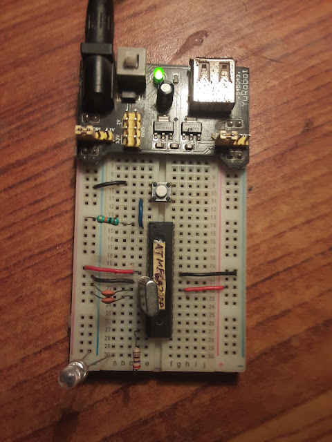
The following picture shows the ATmega328p microcontroller on a Breadboard with 5V regular supply module. The picture shows basic connection required before programming the ATmega328p.

In the picture, a 16MHz crystal is connected to pins 9 and 10 of the microcontroller, and two 22pF capacitors from each oscillator legs is connected to ground. The VCC pin 7 and AVCC pin 20 are connected to +5V rail with wires(red wires). Similarly, the ground pins pin 8 and pin 22 of the micrcontroller are connected to the ground rails. The microcontroller pin 1 is the reset pin. This reset pin is pulled high using 10Kohm resistor, that it is connected to +5V rail using 10Kohm resistor. Similarly the same reset pin is connected to one end of the push button and the other end of the push button is connected to the ground. When the push button is pressed, the reset pin goes low and it resets the microcontroller(meaning it starts reading from the start of the program code). A 270Ohm resistor is connected to Port B pin 0(or pin 14) at one end and the other end of the resistor is connected to the positive end of the LED and the negative end is connected to the ground rail.
The same connection above is shown in schematic diagram below. Notice that the +5V regular supply module is not shown.

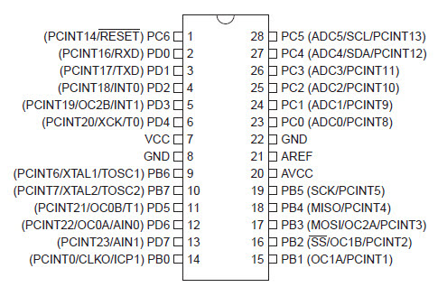
For reference purpose the ATmega328p pin diagram is shown below.
Next we explain how to connect AVR ISP MKII programmer tool to the ATmega328p microcontroller on the breadboard.
Below is picture of AVR ISP MK2 which shows 6 connector output(on the other side is USB connector which is not visible but is connected to the PC or Laptop).

It has 6 connecting pins(RST, SCK, MISO, MOSI, VCC, GND).

The VCC and GND connectors should be connected to the +5V and ground rails respectively. The RST or RESET connector should be connected to the Reset pin or pin 1 of the microcontroller on the breadboard. Similarly the SCK, MISO and MOSI of the connector should be connected to the pin 19, pin 18 and pin 17 of the ATmega328p microcontroller on the breadboard respectively.
The diagram below illustrates this.

After connecting the AVRISP MK2 connector to the ATmega328p microcontroller on the breadboard, it will look like the following.

Beware that the wire color in the above picture does not match the illustrated picture of the connector diagram above.
Once you have completed the AVR ISP MK2 connection to the breadboard, you should connect the USB of the tool to your PC or Laptop.
After this we are complete with hardware connection, breadboarding the ATmega328p for LED blinking. Next we need to write program and burn that into the microcontroller.
2. Writing Program Code in ATMEL Studio 7
First we will write LED blinking program in ATMEL Studio
Open ATMEL Studio, go to File > New > Project

Then in the project wizard window that comes up, select GCC C Executable Project and provide some name for your project like LED_Blink and browse/create/name a folder where you want to save your project. Then click OK.

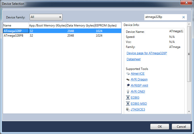
In the next window select or search for the ATmega328p microcontroller you want to work with as shown below. Then click OK.
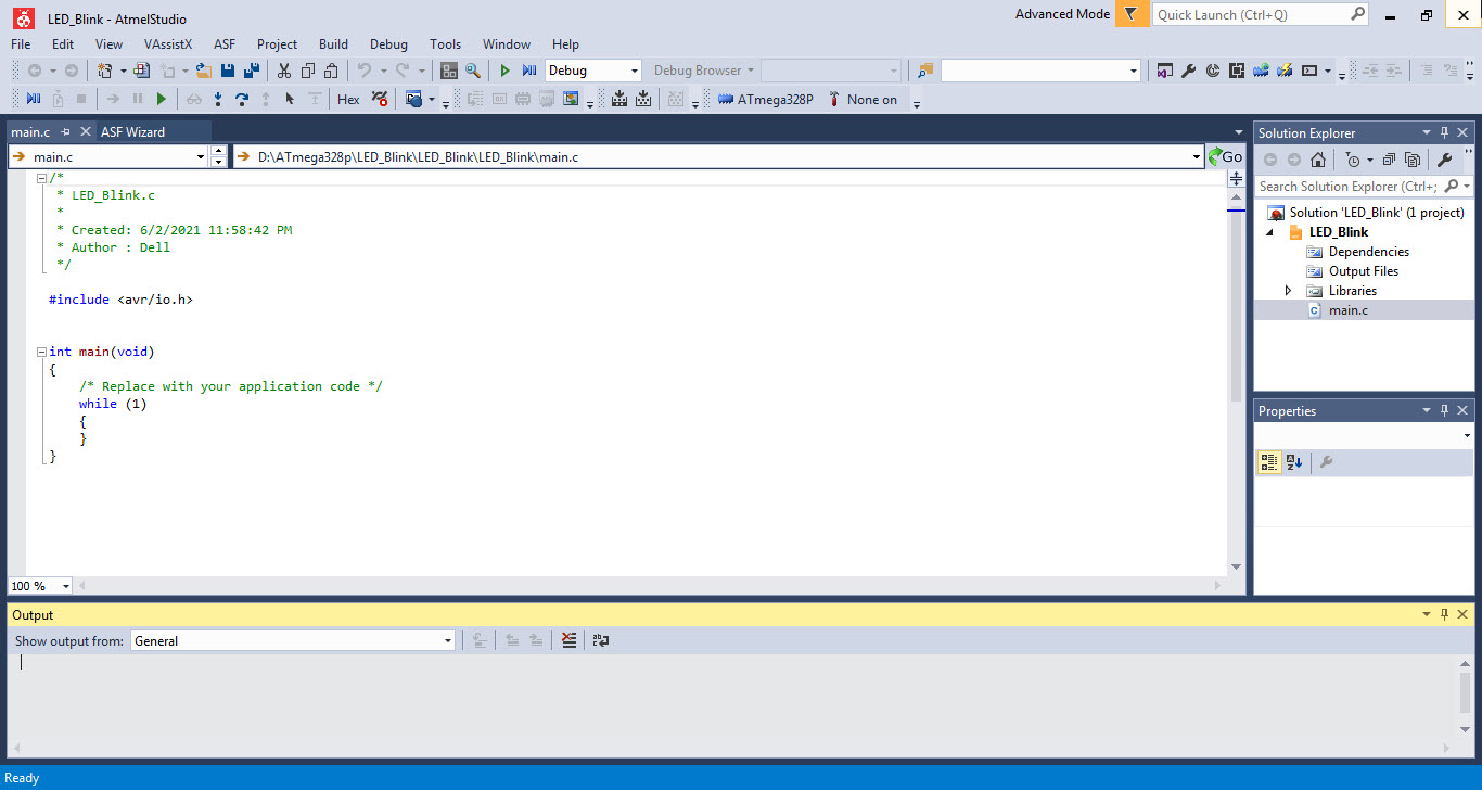
The project solution will open along with the code editor where you can see default C program for the microcontroller.
Now in the code editor we write our LED blinking program. Here we will connect a LED via 330Ohm to Port B pin 0. So we will write our program to send 1 and 0 to Port B pin 0 with 500ms delay between them.
C Program for LED Blink
The program is as follows and you should type the same code in your editor.
#ifndef F_CPU
#define F_CPU 16000000UL
#endif#include <avr/io.h>
#include <util/delay.h>
int main(void)
{
/* Replace with your application code */
DDRB |= (1<<PB0);
while (1)
{
PORTB |= (1<<PB0);
_delay_ms(500);
PORTB &= ~(1<<PB0);
_delay_ms(500);
}
}
Once you have written the program, it should look like the following.

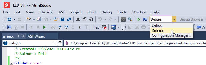
Now at the top bar change Debug to Release as shown below.
Then go to Build menu and click on Build Solution. After the build process, if everything went with problem you should see Build Succeeded in the output window at the bottom. See this in the following picture.

If you now navigate to your project folder, you should see a folder named Release and within it you should find your HEX file(here called atmega328p.hex).
Now this hex file will be uploaded into the ATmega328p microcontroller. To do that, go to Tools > Device Programming as shown.

In the window that pops up, select the AVRIS mkII as Tool, ATmega328p as Device, ISP as Interface and then click on Apply. If the tool is recognized click on the button Read under the Device Signature. Now if your ATmega328p microcontroller is recognized then you will get signature id displayed. Also there should be voltage reading displayed under the Target Voltage field. This is as shown below.

Now we have to set up the fuses. By default the ATmega328p chip is configured to use internal RC oscillator with 8MHz frequency. Since we want to use external 16MHz crystal oscillator we have to make changes to fuses setting.
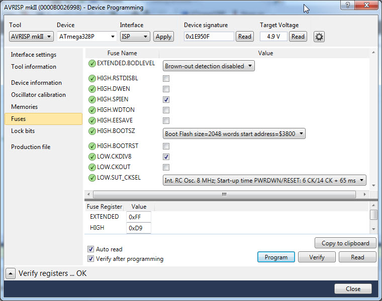
Go to the fuses section and you will see the default fuses setting as shown below.
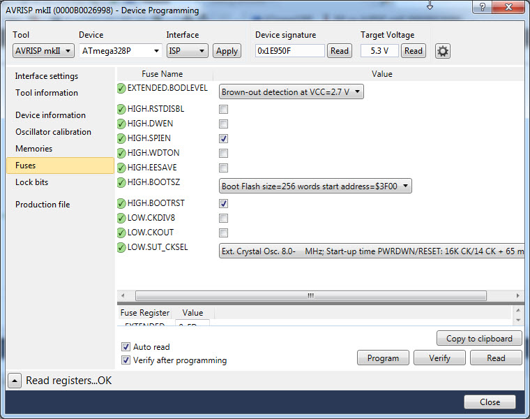
Now uncheck the checkbox of LOW.CKDIV8 and from dropdown menu select Ext.Crystal Osc. 8.0- MHz:Start-up time PWRDWN/RESET:16K CK/14 CK+65ms as shown below.
Then go to memories and using the browse button, select the LED_Blink.hex file which we created earlier from the Release folder of your project folder. Once selected click on Program button. If the uploading process was sucessful then you should see message:
Erasing device… OK
Programming Flash…OK
Verifying Flash…OK
This is as shown.

Once you have done that the LED should be blinking.

Watch the following video demonstration of programming ATmega328p with ATMEL Studio and AVR ISP MKII.
You might be interested in other ATmega328p tutorials:


