
The application of numerical relay technology to busbar
protection has lagged behind that of other protection
functions. Static technology is still usual for such
schemes, but numerical technology is now readily
available. The very latest developments in the
technology are included, such as extensive use of a data
bus to link the various units involved, and fault tolerance
against loss of a particular link by providing multiple
communications paths. The development process has
been very rigorous, because the requirements for busbar
protection in respect of immunity to maloperation are
very high.
Related Article: Busbar Protection
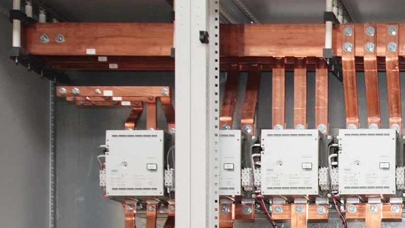
Feeders
each have their own processing unit, which collects
together information on the state of the feeder (currents,
voltages, CB and isolator status, etc.) and communicates
it over high-speed fibre-optic data links to a central unit.
For large substations, more than one central unit may be
used, while in the case of small installations, all of the
units can be co-located, leading to the appearance of a
traditional centralised architecture.
For simple feeders, interface units at a bay may be used
with the data transmitted to a single centrally
located peripheral unit. The central unit performs the
calculations required for the protection functions.
Available protection functions are:
- protection
- backup overcurrent protection
- breaker failure
- dead zone protection
 |
| Architecture for numerical protection scheme |
In addition, monitoring functions such as CB and isolator
monitoring, disturbance recording and transformer
supervision are provided.
Because of the distributed topology used,
synchronisation of the measurements taken by the
peripheral units is of vital importance. A high stability
numerically-controlled oscillator is fitted in each of the
central and peripheral units, with time synchronisation
between them. In the event of loss of the
synchronisation signal, the high stability of the oscillator
in the affected feeder unit(s) enables processing of the
incoming data to continue without significant errors
until synchronisation can be restored.
The peripheral units have responsibility for collecting the
required data, such as voltages and currents, and
processing it into digital form for onwards transmission
to the central unit. Modelling of the CT response is
included, to eliminate errors caused by effects such as CT
saturation. Disturbance recording for the monitored
feeder is implemented, for later download as required.
Because each peripheral unit is concerned only with an
individual feeder, the protection algorithms must reside
in the central unit.
Related Article: Fundamentals of Generator Protection
The differential protection algorithm can be much more
sophisticated than with earlier technology, due to
improvements in processing power. In addition to
calculating the sum of the measured currents, the
algorithm can also evaluate differences between
successive current samples, since a large change above a
threshold may indicate a fault – the threshold being
chosen such that normal load changes, apart from inrush
conditions do not exceed the threshold.
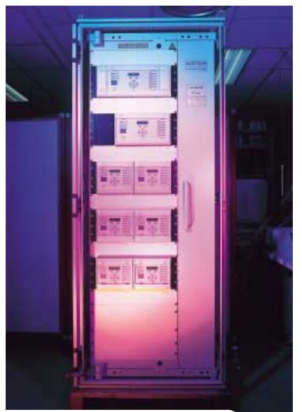 |
| Busbar protection relay using the latest numerical technology (MiCOM P740 range) |
One advantage gained from the use of numerical
technology is the ability to easily re-configure the
protection to cater for changes in configuration of the
substation. For example, addition of an extra feeder
involves the addition of an extra peripheral unit, the
fibre-optic connection to the central unit and entry via
the MMI of the new configuration into the central unit.
Reference:
- Network Protection and Automation Guide | Download


