

In this tutorial you will learn various ways to control a Servo Motor using Simulink and Arduino. This tutorial can be helpful for learning mathematical modeling and algorithm development where servo motor is used. In order to drive a servo motor, signal is required. Here we illustrate how you can use various signal generators like Pulse generator, Repeating sequence, Sine Wave in Simulink and Potentiometer to control a servo motor in real time.

A servo motor is basically a DC motor with gear, shaft and arm whose angle can be precisely controlled. Hence it is used in application area where precise position of motor arm is important. Servo motors are used in robotics, industrial and manufacturing automation etc.
Simulink is Matlab software based graphical programming language where you can use mathematical component with hardware blocks to create dynamical model of systems and simulate, view outputs and tune parameters. With Simulink Support Package for Arduino Hardware library you can use Arduino hardware blocks to design a model, test algorithms, simulate in real time with real world data and then program Arduino.
Configuring Simulink Modeling Environment for Arduino Simulation
In order to complete this tutorial you will need to know several things such as hardware support package installation, where to find blocks in the library required for this tutorial and configuring simulink for simulation and code deployment with hardware. These aspects are explained next.
A. Install Simulink Support Package for Arduino Hardware
To model and program Arduino control of Servo Motors using Simulink, you need to first install Simulink Support Package for Arduino Hardware. How to install this package is explained in the Programming Arduino using Matlab/Simulink Setup tutorial.
Once you have the the library installed, create a new simulink model, open the library browser and go to the Simulink Support Package for Arduino Hardware. Within it go to the common library section and you will see various hardware blocks supported by simulink for arduino. In this tutorial we will mainly using the Standard Servo Write block, Analog Input block and the PWM block.

B. Sources and Sinks
We will also be using various inputs blocks like Pulse Generator block, Repeating Sequence block, Sine wave generator block which you can find in the Simlink > Sources section in the simulink library as shown below.

And we will also use the Time Scope and Display blocks which you can in the Simulink > Sinks section of the simulink library as shown below.

C. Hardware Setting/ Arduino Board Configuration
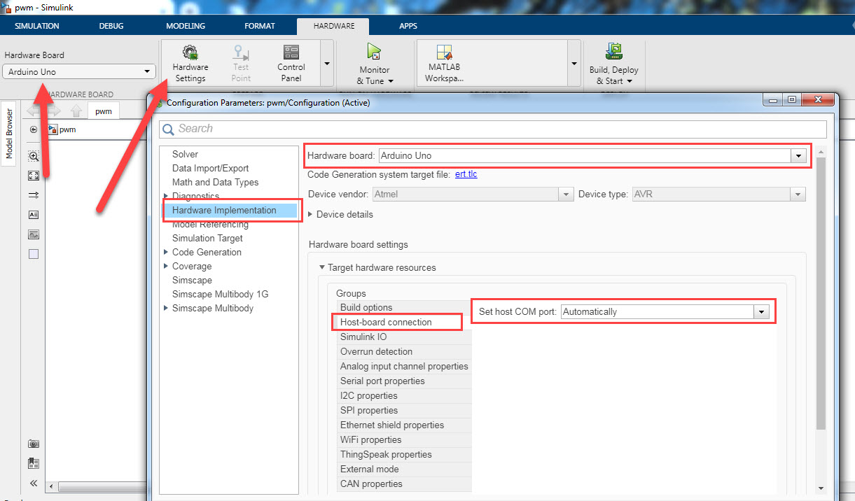
To run/deploy the simulink model onto the Arduino, you have to configure the which Arduino board you are going to use and what COM port your Arduino board is connected to. For this go to the HARDWARE Tab, then double click on the Hardware Settings. In the window that pops up, select Hardware Implementation and then select the Hardware Board you want to use. In this tutorial we are using Arduino Uno. After selecting the board, click on the Target hardware resources and set the COM port number to which your board is connected in the Host-board connection option. In our case as shown in the figure below, the Host-board connection > Set host COM port is set to Automatically. If any error occurs regarding COM port connection, check this setting. You can also optionally set the COM port manually.
Example 1: Servo motor control using Pulse Generator
The first example of controlling a Servo Motor is using the Pulse Generator block. As already mentioned the Pulse Generator block is found in Simulink> Sources in the simulink library.
Servo Motor Simulink Model
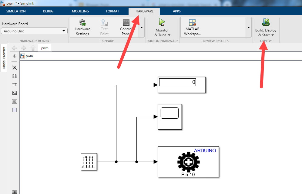
Create a new simulink model, save it with some name and place the Pulse Generator block into the model. Also place the Standard Servo Write block found in Simulink Support Package for Arduino Hardware > Common library section and the Time Scope and Display blocks found in Simulink>Sinks library into the newly created model. Then interconnect the blocks and create the servo simulink model as shown in the figure below.

Configure the Pulse Generator as shown in the picture below.
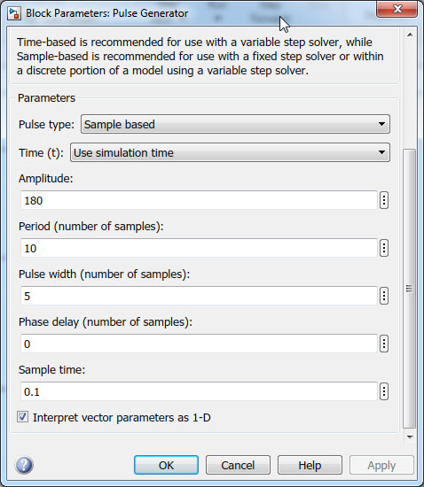
The pulse we generated is of amplitude 180 degree, with period of 10 samples and pulse width of 5 samples. The sample time is 0.1 seconds. Hence in terms of time, the period is 10 samples*0.1 seconds/samples = 1 second and pulse width is half the pulse period so the pulse width is 0.5 seconds.
Interfacing Arduino with Servo Motor
Before you start the simulation, the Arduino and the Servo motor should be connected. This is as shown in the figure below. The ground and power supply pin of the Servo Motor should be connected to the ground and +5V of the Arduino UNO. The signal pin of the Servo Motor should be connected to the digital PWM pin 10 of the Arduino UNO.

Simulation and Code Deployment to Arduino
Monitor & Tune
To start servo motor simulation in real time without deploying permanently the program code into Arduino Board you can use the Monitor & Tune button in the HARDWARE tap. Click on it to start the real time simulation on Arduino board.

The process of building the model, initialization process internal to simulink will start. A code generation report for the model will be made available by simulink like the one shown below.

You should also see the Diagnostics report generated by simulink.

Once the simulation starts running, you should see the Servo Motor arm rotating. Following video demonstrates real time simulation of servo motor control with Arduino using Simulink graphical programming.
You should also see the Pulse signal displayed on the time scope which is shown below.

At this time, we are running simulation in real time but the program code is not deployed permanently into Arduino board. So at this time you can make changes in your model, fine tune any parameters like pulse width or period in your model.
Build, Deploy & Start
After you are satisfied with the algorithm model, the next step is to deploy the program into Arduino board. The deployment of the code generated by simulink into Arduino UNO means that Arduino will control the Servo motor independently of simulink. That is the program will run even if you plug out the USB cable.
To program Arduino permanently, go to the HARDWARE tab, click on the Build, Deploy & Start button. This will start the compilation, initialization and building process and at the end the Arduino board will be programmed.
How to deploy the simulink program is shown in the following video.
Example 2: Servo motor control using Repeating Sequence Generator
In this Servo control with Simulink example, we will use repeating sequence block.
Servo Motor Simulink Model
Create a servo motor simulink model as shown in the figure below. The Repeating Sequence block can be found in Simulink > Sources section of the simulink library (see above).

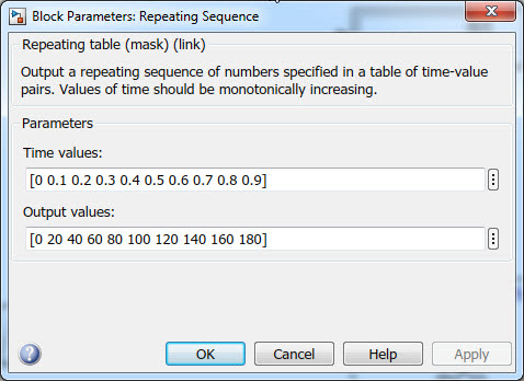
Double click the Repeating sequence block and configure it as shown below. Here we are using time values from 0 second to 0.9 seconds and each time we are sending out angle values from 0 to 180 degree.
Servo Motor with Arduino Interfacing
The hardware interfacing is same as in case of the Pulse generator example explained above and is shown below.
Monitor & Tune
We can now Monitor & Tune to simulate the model in real time and later deploy the code permanently into the Arduino board as in case of the Pulse generator example explained above. Here we will only Monitor & Tune but not deploy the code as this is essentially the same and easy process.
Click on the Monitor & Tune button to start the simulation in real time with Arduino board. As was previously explained in the example 1 of servo control using pulse generator, you will see code generation and diagnostics reports. After that, the motor will start to rotate with each 0.1 second going from 0 degree to 180 degree and repeating this process again. This Monitor & Tune execution and simulation with Repeating Sequence generator to control servo motor is shown in the following video.
You should see the display block showing the output values(angles) and the time scope will show the sequence generated which looks like a ramp signal as shown below.

You can stop the simulation, fine tune the sequence by specifying different time interval with different angles and again run the simulation. After you are satisfied with the motor control algorithm, you can then move on the actual deployment of the program code into Arduino board.
Example 3: Servo motor control using Sine Wave Generator
In this servo motor control example with Arduino Simulink, we will use sine wave generator.
Servo Motor Simulink Model
Make a servo motor simulink model like the following. The Sine Wave block can be found in Simulink > Sources section of the simulink library (see above).

Double click on the Sine Wave generator block and enter the following values.

Monitor & Tune
Next step is to simulate the servo motor simulink model. Click on the Monitor & Tune button from the HARDWARE tap. The simulink will start compiling, initialization and building process. You will see code generation and diagnosis reports window pop-up during this process. After completing the process, the servo motor will start to rotate with frequency of 0.5Hz, from 0 to 180 degree.
The following video demonstrates control of servo motor using sine wave. As you will notice the motor moves very slowly but very smooth at the frequency 0.5Hz. By changing the frequency to a more value like 1Hz or 10Hz, the servo motor will faster.
The display block will show the amplitude and the time scope will the sine wave waveform as shown below.

Example 4: Servo motor control using Potentiometer
In this example of servo control using simulink and arduino we will use a potentiometer to control the servo motor position.
Servo Motor Simulink Model
For this example we will be using Analog Input block from the Simulink Support for Arduino Hardware library for the potentiometer input signal to the Arduino UNO. The following is the simulink model to read analog signal from potentiometer and send to Standard Servo Write block to control Servo motor.

Here the Arduino Input block configured with analog pin 0 is set with 0.01 sample time as shown below.

The Gain block has value 180/1023 because the Standard Servo Write block accepts angle value from 0 to 180 degree and the ADC input from analog input ranges in value from 0 to 1023 because the Arduino UNO has 8 bit resolution(10^8-1 = 1023).

Hardware Interfacing of Arduino, Servo Motor and Potentiometer
For this demonstration, the Arduino pin 10 is connected to Servo motor signal pin. A 10KOhm potentiometer is used whose middle pin is connected to the Analog pin 0 of the Arduino. The servo motor, potentiometer should share the same common ground. This hardware interfacing is shown below.

Simulation: Monitor & Tune
Click on the Monitor & Tune button. This will start the compilation, building and initialization process for the real time simulation on Arduino UNO board. After completion of build process, rotate the knob of the potentiometer. In response, the Servo Motor arm will rotate to the position corresponding to ptentiometer knob position. The following video shows this.
You should also see the analog value in degree displayed in the display scope and the analog value plotted in the time scope as shown below.

Simulink PWM control of Servo Motor
Here we will show an alternative way of the above example of servo control using potentiometer. In the above example we have used the Standard Servo Write block but since Servo motors are controlled using PWM signal we can also use the PWM block.
So here we will not use the Standard Servo block but instead use the PWM block. As before, we will read the voltage from the Arduino analog pin 0 and convert it PWM value(0 to 255) value using the Gain block with value 255/1023 and send that PWM value to PWM pin 10 where the servo motor is connected.
The hardware connection of interfacing Potentiometer with Arduino and Servo motor is the same as before.
Servo Motor Simulink Model
The simulink model for this case looks like the following.

The following video demonstrates how to use the PWM block with analog input block to control a servo motor.


