– Advertisement –
Imagine a smartwatch whose display acts as an interface serving you both as a keyboard and a mouse! What if I tell you that it’s easily possible.

Previously, in March 2023 issue, we published a project for a smartwatch with an ESP32 board featuring Wi-Fi analysis and health monitoring capabilities. Building upon this, let us now create a smartwatch that can function as a wearable human interface device (HID). This watch can serve as both a keyboard and a mouse, providing control over phones, laptops, etc. It acts as a portable keyboard with mouse functionality, worn on the wrist.
– Advertisement –

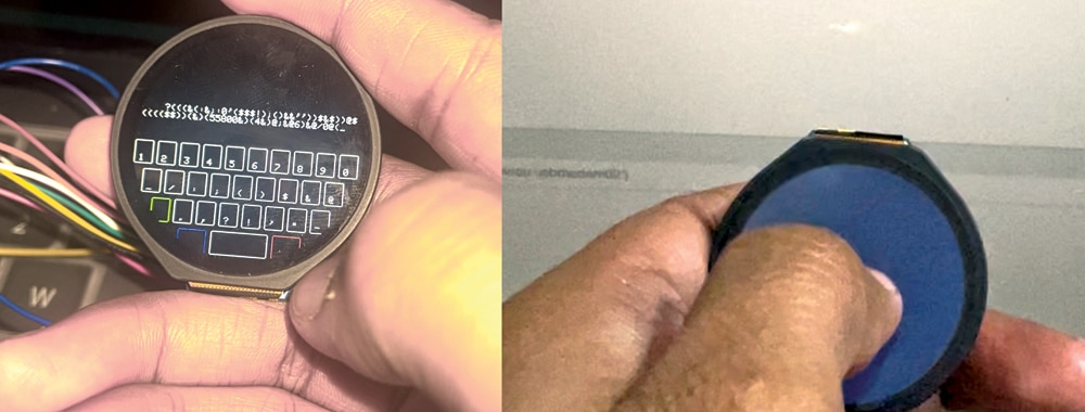
This design utilises the board called Indusboard coin along with GC9A01 driver and CST816S capacitive touch driver-based display, perfectly suited for a round display. The display is connected to the Indusboard using SPI and I2C pins onboard. Refer to Fig. 1 for the author’s prototype. The components required for this device are listed in Bill of Materials table.
| Bill of Materials | ||
| Components | Description | Quantity |
| Indusboard | Development board | 1 |
| USB Type C | Adaptor | 1 |
| Round touch display | GC9A01 driver and CST816S capacitive touch driver | 1 |
Software coding
The code is created using Arduino and the TFTeSPI library, with the CST816S touch driver library driving the display and touchscreen. The HID library comes pre-installed with the ESP32S2 Board SDK, so only TFTeSPI and CST816 libraries need to be installed. Search for them in the Arduino library manager and install. Configure the display driver and SPI pins in the TFTeSPI library folder found in the Arduino library folder. Open the user config file for the library and uncomment the GC9A01_Driver. Set the MISO, MOSI, CS, and DC pins in the configuration file. Refer to Figs. 2 and 3 for settings.

Now, two codes need to be written: one for the touchpad mouse and the other for the keyboard.

Code for touchpad mouse. For the mouse, include the mouse HID library and define the I2C pins for the display. Any pin on the Indusboard can be used as the I2C pin. Here, the pins 5 and 6 are used as SDA and SCL for I2C pins. In the code, map the touch points with mouse movements and use gestures like left swipe, right swipe, single tap, and double tap for mouse clicks. Refer to Figs. 4 and 5 for code snippets.


Code for keyboard. Include the HID library for Indusboard and set the I2C pins of the touch display driver. Any pin on the Indusboard can be configured as an I2C pin. Here, the pins 5 and 6 are used. Refer to Fig. 6 for code settings.

Create the keyboard layout, display it on the keyboard, map the touchpoints to the displayed keys, and detect touch on those keys. Then, send that letter as HID input to the laptop. Refer to Fig. 7 for the code snippet for the keyboard. Fig. 8 shows the code snippet to detect the touch point and send as HID input.

After including all the libraries, upload the code by selecting the ESP32S2 as the chip and the right port.

Circuit diagram
Connect the display and touch pins according to the circuit diagram shown in Fig. 9. Solder the pins behind the Indusboard. The Indusboard size fits perfectly behind the display like a watch. Refer to Fig. 10 for soldering and placement of the Indusboard.

Testing

After proper assembly, power the Indusboard. When the code for the keyboard is uploaded, it shows the keyboard layout, and touching the keys will type the corresponding alphabets and letters. When the code for the mouse is uploaded, moving a finger on the display will move the mouse pointer along with the touch movements. Refer to Fig. 11 for the author’s testing of the smartwatch touch keyboard.

